
Which Radio Shack no longer carries, is still available from internet sites. The FET transistor circuit uses a 2N3819, For minimal noiseĪnd best performance use the LMC6001AIN. IC circuits to use would be the LMC6001CIN, LMC6041, LM4250. Integrated circuits, or Op-amp ICs have been improved much over the years. Suggested A low noise design is essential for optimum sensitivity. Operational amplifier The second stage of the block diagram is the

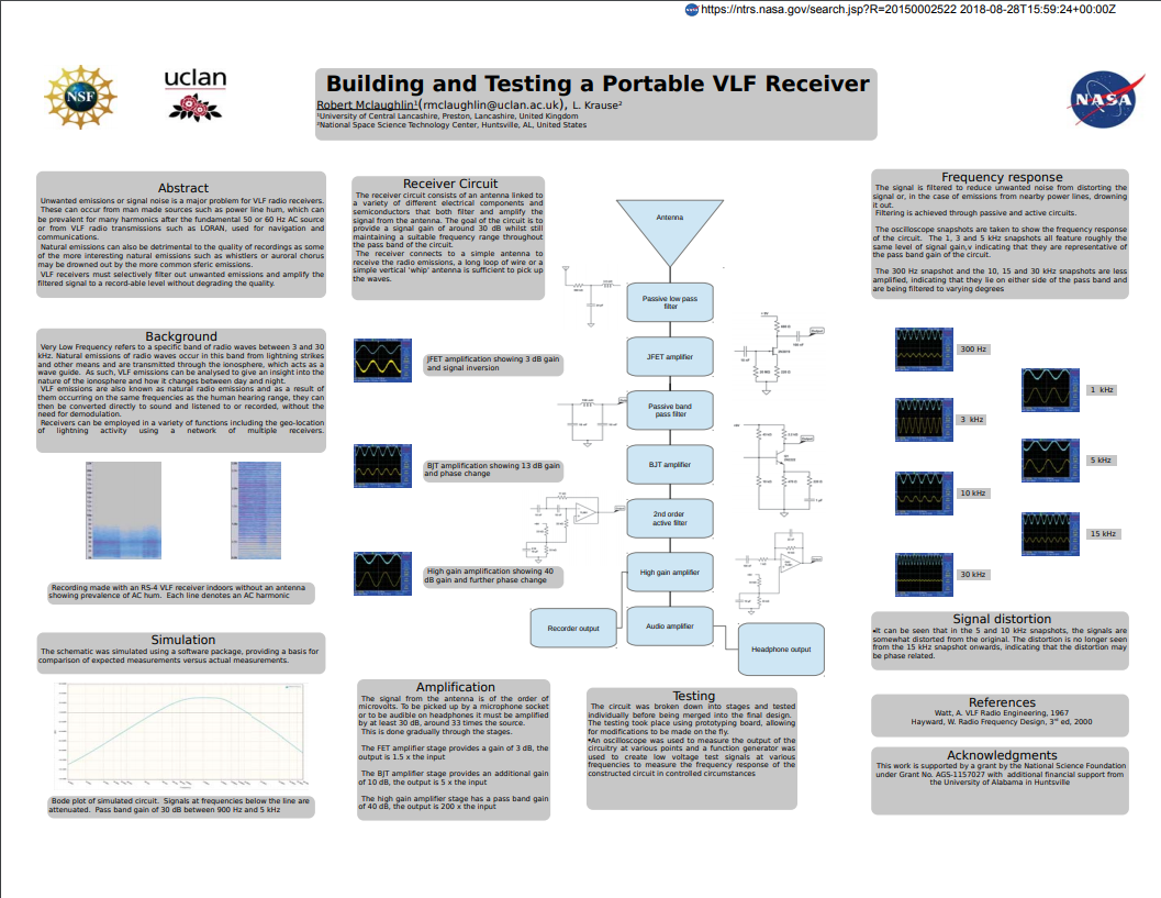
Keep in mind that more complex filters are needed for receivers with long Here are some sample circuits to start out with. The values of these components are most important. Right is the high impedence low pass filter. Looking at the block diagram, the first stage starting from left going Select from short whip to long wire antennas which is a no-brainer Lesser degreeįiltering does improve gain somewhat, but invites out of band Length means additional filtering will be needed. Signals.Undesirable signals become more evident as The receiver is the most susceptible section to unwanted The most important factor in VLF radio design is the use of low Section, providing it is put in it's proper place. To work together one block section will connect directly with another Looking at the overall structure of a good receiver design.
VLF RECEIVER ANTENNA. HOW TO
To construe how to goĪbout building a receiver we must first get the basics down. In fact, a full-length VLF antenna wouldīe about 60 MILES long! A small antenna produces very little signalĬurrent for reception, however, a high gain, high impedanceĪmplifier can make up for the difference. A typical verticalĪntenna for VLF reception is usually less then 60 feet long someĪre even less then 10 feet. Length to the resonant frequency wavelength. The reason for this comes from the ratio of actual antenna Electromagnetic relatesĮ-Field receivers must use a very high input impedance to detect Electrostatic pertains to theĬharge voltage or current wave of the signal. There are two ways to intercept a VLF signal: electromagnetically (B-Field) What kind of recording equipment will be.Will it be near or far from power lines?.The first step in building a receiver is to consider these questions These circuitĮxamples are optimized to design a receiver specifically for Natural Radio recording and listening.

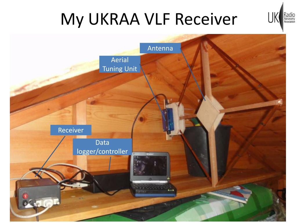
Tuning as well, we are just going to keep it simple here for now. More advanced VLF receivers do use frequency conversion and digital Most Natural Radio or VLF Receiver circuits are tunedįor ULF, ELF and VLF bands or 100 hertz to 15 Kilohertz (see band allocation chart) Receiver is that it is already tuned for audio frequencies. Is passed on to the amplifier stage to drive the speaker or headphones. Knowledge of electronic circuitry and fundamentals.įrequency conversion to change and then demodulate the radio signal into an audio signal which You can click on the images to enlarge them.The information here is most helpful to a person with a Here is the original frame front and back. The theoretical values have been calculated from the equation described in the page dedicated to the loop antenna theory. The author has built two of those antennas and has measured the following characteristics: About 150m (500ft) long.įor the cable: RG-58 Coax cable (length as needed) and two male 50Ω TNC connectors. Magnet wire (solid copper wire with varnish insulation) #26 (diameter 0.4mm - cross sectional area 0.13mm²). It has to be at least 35mm (1-3⁄8″) deep. One frame 70x100cm (27-½ x 39-¼″) Ikea RIBBA or similar. The following items are necesary to build the antenna: The dimensions and the wire wounds do not have strict tolerances. The antenna consists of 40 to 50 turns of copper wire wounded around a 60cm (24″) square frame. This design is small, simple and relatively easy to "hide". For our purpose, the antenna does not need to be tuned and many designs are possible.


 0 kommentar(er)
